Showing posts with label Project. Show all posts

Sunday, February 16, 2020

Build: Spark Plug Tester

Beware of 25,000 volts!
A few years back, I had the incredible opportunity to take on a commissioned project for a dear friend of mine. The task at hand? Building a spark plug tester from scratch. It was an exciting challenge that allowed me to put my skills to the test and dive into the world of automotive engineering. Today, I want to share with you the story of how this project came to be and the journey I embarked on to bring it to life. After much delay and anticipation, I am thrilled to finally share my latest work with all of you. Life has a funny way of throwing curveballs, and unfortunately, publishing this piece took longer than expected. But hey, better late than never, right? 

So, without further ado, here it is! Pouring my heart and soul into this project has been an incredible journey. From the initial spark of inspiration to countless hours of research and writing, every step of the process has been a labor of love. Ah, let me tell you about the exhilarating journey I embarked on with this project. 
Example of a spark plug cable replacement part.
Courtesy photo from ProtonPeroduaParts.com.my
It wasn't just about tinkering with electronics; oh no, it was so much more than that. The true thrill lay in the art of constructing the very foundation for the spark plug. When it comes to purchasing spark plug cables, your best bet is to head over to your local auto parts shop. There, you'll find a variety of options that include both the cable and ignition coil insert. However, it's important to note that some of these cables may be on the flimsier side. 

Unfortunately, they may not come with a latch or any mechanism to securely attach them to the construction box. So, I made the bold decision to embark on a thrilling adventure - building my very own creation from scratch. In my latest project, I decided to delve into the world of high-voltage generators. To achieve this, I opted for an old flyback transformer salvaged from a CRT TV.  I couldn't resist the allure of repurposing this vintage piece of technology to power my circuit. 

As you scroll through these images, you'll witness the transformation from mere blueprints. I am thrilled to share with you a project that has brought me immense joy and satisfaction. I sincerely hope that you will find it equally enjoyable, and I eagerly await your feedback and any similar projects you may have embarked upon. 


Always test your circuit first on a breadboard

I built the PCB using the toner transfer
technique for this project. Got a pretty good result.

I used the old CRT flyback transformer for this
project and the 2N3055 transistor for the driver

This is what the inside looks like. The left side is the high-voltage
circuit meanwhile the right side is the low-voltage supply


A simple construction of the spark plug holder

The final construction with the protective plastic cover

Close up photo


Thursday, November 27, 2014

My 8x8x8 LED Cube at PMMF14

I spent almost 40 hours to build this. This project test my patience and soldering skill. If you want to build one yourself, follow this site that has a detailed step-by-step instructions with source code. I also purchased an 8x8x8 LED cube kit from eBay which I haven't construct yet. Will post it up once is done. 

I showed this during the Penang Mini Maker Faire 2014 together with my friend's LED Message Board and 3D Cube booth. 


Monday, September 29, 2014

Build: Vintage Sign Board with Running Lights - Part 3

Hi! Welcome back and staying with me for part 3 of my project - The Wiring & Electronics for the vintage sign board project. I know it has been 6 weeks since from the last update on my blog. I was busy to welcome a new member into my family. I'm now a dad to my beautiful daughter. It was a joyful and happiest moment in my life.

Okay, back to my project. If you were wandering what was I trying to build with the ATTiny13 microcontroller which I posted on my blog on 15-June-14, here is the answer. To build a simple running lights using Arduino on ATTiny13 chip. Basically I needed 2 inputs and 2 outputs for the switches and a pair of lights. With the UNO or the MINI would probably under utilize and also not cost efficient. So, I decided to use the ATTiny13 which I had a few lying around on my table. I managed to get the tips from the open-source community on how to program the ATTiny13 with Arduino core easily. Refer to the link for more information.

The circuit consists of  a +5V regulated power supply for the entire board, the main controller and lastly the high voltage AC circuit to drive the incandescent bulbs. The optoisolator MOC3023 purpose is to drive the triac and isolate between the high voltage and low voltage circuit. I picked the BTA12-600 triac for this project to drive nine 230V AC bulbs at each time. The connection MT1 and MT2 should be correctly connected to Neutral  and Live wire in order to work correctly. I had some problem earlier due to wrongly connected. Please be reminded that this part of the project involved high voltage electricity and can be fatal. If you're not sure, please consult a professional or don't do this project. Below is the schematic diagram.


Friday, August 22, 2014

Build: Vintage Sign Board with Running Lights - Part 2


Part 2: The Wood Frame Board
The woodworking part was the easiest part of the project. With the right tools available, woodworking can be very exciting and fun. The wood materials are not difficult to find and is inexpensive. I bought a piece of 2 1/4 inches width x 1 inch thickness x 8 feet wood for the frame and I had left over of 2 cm thick plywood from previous project used for the back ground board. Then I used a heavy duty stapler instead of screws and nails to hold the pieces together and shellac for the finishing.

Here were the tools I used for this part of the project: jigsaw, palm sander, bench drill, cordless drill, mitre guide, tenon saw, ruler, protractor, palm router, workbench stand, shellac and heavy duty stapler. Total 4 hours time spent.


Saturday, August 16, 2014

Build: Vintage Sign Board with Running Lights - Part 1


Introduction
I made this project for my cousin's wedding reception. I was working with his brother-in-law from the beginning on an idea of vintage display board with the "Now Showing" sign. To make it look classic, I use the incandescent light bulbs like the one we see at the old theater sign board. Then equipped with 4 running light patterns (including ALL ON) to make it interesting.

Me posing with the sign board at the wedding night


There are 3 parts in this project.
Part 1: The Paper Lettering
Part 2: The Wood Frame Board
Part 3; The Electronics & Wiring
This project involved arts & crafts, woodworking, wiring and electronics skills.


Saturday, July 12, 2014

A Simple PowerPoint Control Foot Switch

As a guitarist in a praise & worship session, I will have problem flipping my lyrics with chords on the paper while I'm playing. I have to pause a little while and quickly flip the pages or press enter on my laptop if the lyrics is in the PowerPoint slides. This will cause a moment of interruption on my strumming. In order to solve this problem when I'm using my laptop to refer the chords and lyrics, I built a simple foot switch control to change the slides using an al'cheapo USB keypad which you can get it from the computer shop with less than RM20.
 My PowerPoint Foot Switch Control Box

Monday, June 30, 2014

PCB UV Exposure Box

One of the coolest stuff that I made was the PCB UV exposure box. Over the years I've been using my table lamp as the light source to expose my presensitized PCBs. There have been failures and successes using the table lamp. Quite a number of incidents of over exposing and will have to redo. And is quite expensive to buy a presensitized board here. So, last year I decided to build one and never to face these problems again.

My old method using the table lamp to expose the PCB
My homemade PCB UV Exposure Box
The box is made out of MDF (medium density fibreboard) board recycled from a packing box. The piece of glass was from a picture frame I bought from a RM2 shop in Taiping. The rest of the items such as UV lamps and electronic ballasts were bought from a local electrical store, Thye Huat. Below are some more photos and please visit my Instructables website for the steps-by-step instructions and the materials I used.

UV lamps
Reused MDF boards that cut into sizes
Completed box with the cover
Here is the result

Thursday, June 26, 2014

One man's trash is another man's treasure

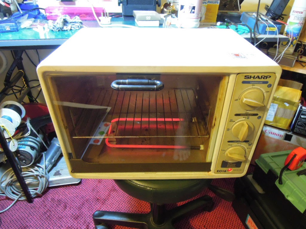
Guess what I found at the recycle collection area at my apartment just now. I was searching for a used oven since a year ago. Believe it or not, is still working perfectly. Guess what I'm planning to do with this oven?


To bake cake...Nope. But if you guess as a reflow oven...you're right! What is a reflow oven? Generally is an oven for reflow soldering of electronic components onto the printed circuit board (PCB). It will be useful for producing a lot of PCBs with SMT components.

Some modifications will be required before I can use as a reflow oven. I will build a controller board that will measure the temperature and control the heating element following a predefined profile temperature. Another exciting project coming up!


Proposed basic block diagram of the controller for reflow oven